

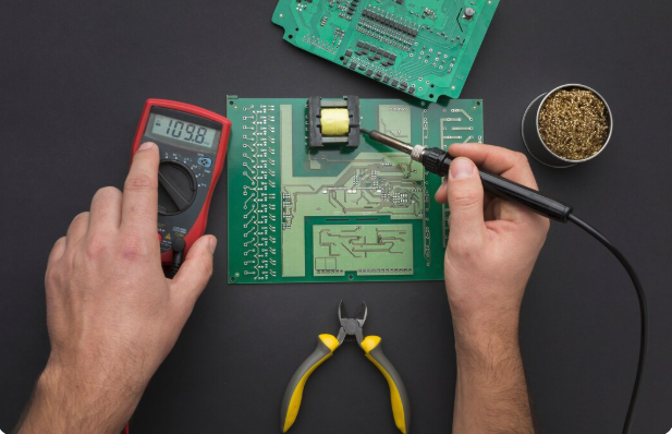
Printed circuit boards (PCBs) often require a reliable way to connect different components, wires, modules, or sections of an electronic system. PCB connectors are designed to create these connections while allowing electrical signals or power to pass between the circuit board and external components.
One common type is the 雙排針, or dual-row pin header. This connector arrangement features two parallel rows of pins and is commonly used where multiple electrical connections are required within a compact space.
What Is a Dual-Row Pin Header?
A dual-row pin header is a type of PCB connector consisting of two parallel rows of metal pins arranged at a fixed spacing. The pins are mounted directly onto a printed circuit board and can connect with compatible sockets, female headers, ribbon cable connectors, or other matching components.
Dual-row configurations can provide a greater number of connections within a relatively compact area compared with a single-row arrangement of the same length.
How Are PCB Headers Used?
PCB headers can serve as connection points between a circuit board and other parts of an electronic system. Depending on the connector design, they may be used for:
- Board-to-board connections
- Wire-to-board connections
- Internal equipment wiring
- Signal transmission
- Power connections
- Programming and debugging interfaces
- Connections to sensors or peripheral modules
The specific use depends on the connector’s electrical ratings, pin configuration, and compatibility with the connected components.
Common Pin Configurations
Pin headers are available in different arrangements to suit various PCB designs.
Single-Row Headers
Single-row headers contain one line of pins. They are commonly used where fewer connections are required or where PCB space is limited.
Dual-Row Headers
Dual-row headers use two parallel lines of pins. This configuration can accommodate a higher number of connections while maintaining an organised layout.
The number of positions can vary, depending on the connector design. For example, a header may be configured with several pins in each row to support multiple signals or connections.
Important Specifications to Consider
Choosing a suitable PCB header requires more than selecting the required number of pins.
Pitch
Pitch refers to the distance between the centres of adjacent pins. The connector pitch must be compatible with the PCB layout and the mating connector.
Number of Contacts
The total number of pins should match the number of electrical connections required by the application.
Mounting Style
PCB headers may be designed for:
- Through-hole mounting
- Surface mounting
- Straight orientation
- Right-angle orientation
The appropriate style depends on the circuit board design and available installation space.
Contact Plating
Connector contacts may use different plating materials or finishes. These can affect properties such as conductivity, corrosion resistance, and long-term connection reliability.
Current and Voltage Ratings
The electrical ratings of the header should be suitable for the intended circuit. Signal connections and power connections may have different requirements.
Straight vs Right-Angle Headers
A straight header extends vertically from the PCB, while a right-angle header allows the connection to extend parallel to the circuit board.
The choice often depends on enclosure space, cable routing, accessibility, and the orientation of the mating connector.
Why Connector Compatibility Matters
A pin header must be compatible with both the PCB footprint and the mating connector. Even if two connectors appear similar, differences in pitch, pin dimensions, number of positions, or orientation can prevent them from fitting correctly.
Before selecting a connector, it is useful to confirm:
- Pin spacing
- Number of rows
- Number of positions
- Mounting style
- Pin dimensions
- Electrical ratings
- Compatibility with the mating connector
Checking these specifications before assembly can help prevent connection or installation issues.
Applications of Dual-Row PCB Headers
Dual-row pin headers can be found in many electronic applications, including:
- Consumer electronics
- Industrial control equipment
- Development boards
- Embedded systems
- Test and measurement devices
- Computer hardware
- Communication equipment
- Prototype circuit boards
Their suitability depends on the specific electrical, mechanical, and environmental requirements of the equipment.
Choosing the Right Connector
When selecting 雙排針 for a PCB design, it is important to consider the number of contacts, pitch, mounting method, orientation, electrical ratings, and mating compatibility.
A properly selected header can provide an organised and reliable connection between the circuit board and other components. Reviewing the complete connector specification before finalising a PCB layout can also help avoid compatibility issues during assembly.
Conclusion
Dual-row pin headers are commonly used to provide multiple electrical connections in a compact and structured arrangement. Their two-row design makes them suitable for a wide range of board-to-board and wire-to-board applications.
By considering connector dimensions, contact configuration, electrical requirements, and compatibility with the PCB and mating component, designers and technicians can select a connector that is better suited to the intended application.
Read More : How Tech Innovations Are Reshaping Personal Confidence Through Modern Procedures
